|
Solenoid Valve Coils
The advantage of the low voltage coils is obviously electrical safety. Hobbyists and do-it-yourselfers often power the low voltage solenoid valves with wall transformers. Most smaller valves 12 VDC valves can be powered by a 12-Volt / 500 mA power supply. However, always make sure your power supply does meet or exceed the power requirement of the solenoid. The 24 VAC solenoid valves appeal to hobbyists as well since they can be easily controlled by irrigation timers. Most industrial applications and heavy machinery use solenoids with 24 VDC coils.
Types of Coil ConstructionSolenoid valve coil construction usually falls in one of the following two categories:
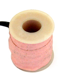
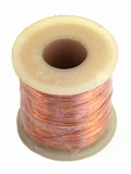
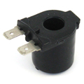
A tape wrapped coil is manufactured by looping conductor wire (also called magnet wire) around a spool or bobbin. The magnet wire has a thin insulation layer around it. The completed winding is then protected by a insulation tape. Thus, the name tape wrapped coil. Encapsulated coils basically follow the same basic principle as the tape wrapped coil. However, instead of being protected by tape, the winding is encapsulated or molded over in suitable resin. Tape wrapped coils are used in applications with relatively mild environments. Tape wrapped coils allow for much smaller production runs. However, tape wrapped coils have a much lower resistance against moisture than encapsulated coils. In addition, encapsulated coils have much stronger lead wires (to protect against pull-out). Coils with DIN ConnectorsValve manufacturers often offer a DIN connector option on their coils. Instead of lead wires, the coil will have prongs or pins to accept a standard DIN connector. The coil is considered to have a male connection and the plug connecting to the coil is a female connector. Using a DIN connector provides many advantages: quick valve or coil exchange, excellent insulation properties, possible water tightness etc. The connector standard used for solenoid valves is DIN 43650 . The DIN 43650 series consists of five connectors, which have the following pin spacing:
DIN connectors can be purchased as shells to be wired by the installer or they may be factory molded with a cable assembly. They have usually contain three or four terminals or pins. Some DIN connectors are available with LED indicators which indicate the power state of the coil for diagnostics purposes. Can the same valve be used with different coils?This depends on the specific brand of the valve. It is often possible to swap coils in order to use a different voltage with the solenoid valve. Latching SolenoidsA latching solenoid valve does not require current to stay in its energized position. Electrical energy is only consumed to open and close the valve, not to keep it in either of those positions. Latching valves are often used in battery powered applications (e.g. automatic faucets) as they only need a pulse power to change open/closed state of the valve. The polarity of the pulses are reversed between the opening pulse and the closing pulse. Hit and Drop"Hit and drop" is technique used for reducing the power consumption of solenoids valve coils. A larger voltage (current flow) is required to energize a valve than is needed to keep the valve in the energized position, making it possible to lower the power consumption of the coil. "Hit and Drop" is also known as 'Pulse and Hold', 'Spike and Hold', 'Hit and Hold', and 'Pick and Hold'. |